The following documents were referred to during the preparation of this specification. In case of conflict, the provisions of this specification shall take precedence.
IEC 129:1975: Alternating Current Disconnectors (Isolators) and Earthing Switches
IEC 60694:2002: Common Specifications for High Voltage Switchgear and Controlgear
BS 729: Hot dip galvanized coating on iron and steel articles
IEC62271-102
Isolator (Disconnector) - a mechanical switching device which provides, in the open position, an isolating distance in accordance with Electrical Safety requirements.
SERVICE CONDITIONS
The isolator shall be suitable for continuous operation outdoors in tropical areas at altitudes of up to 2200m above sea level, humidities of up to 90%, average ambient temperature of +30ºC with a minimum of -1ºC and a maximum of +40ºC and heavy saline conditions along the coast.
DESIGN AND CONSTRUCTION
The Isolator, Solid Link shall be designed and constructed in accordance with IEC 129 and IEC 60694.
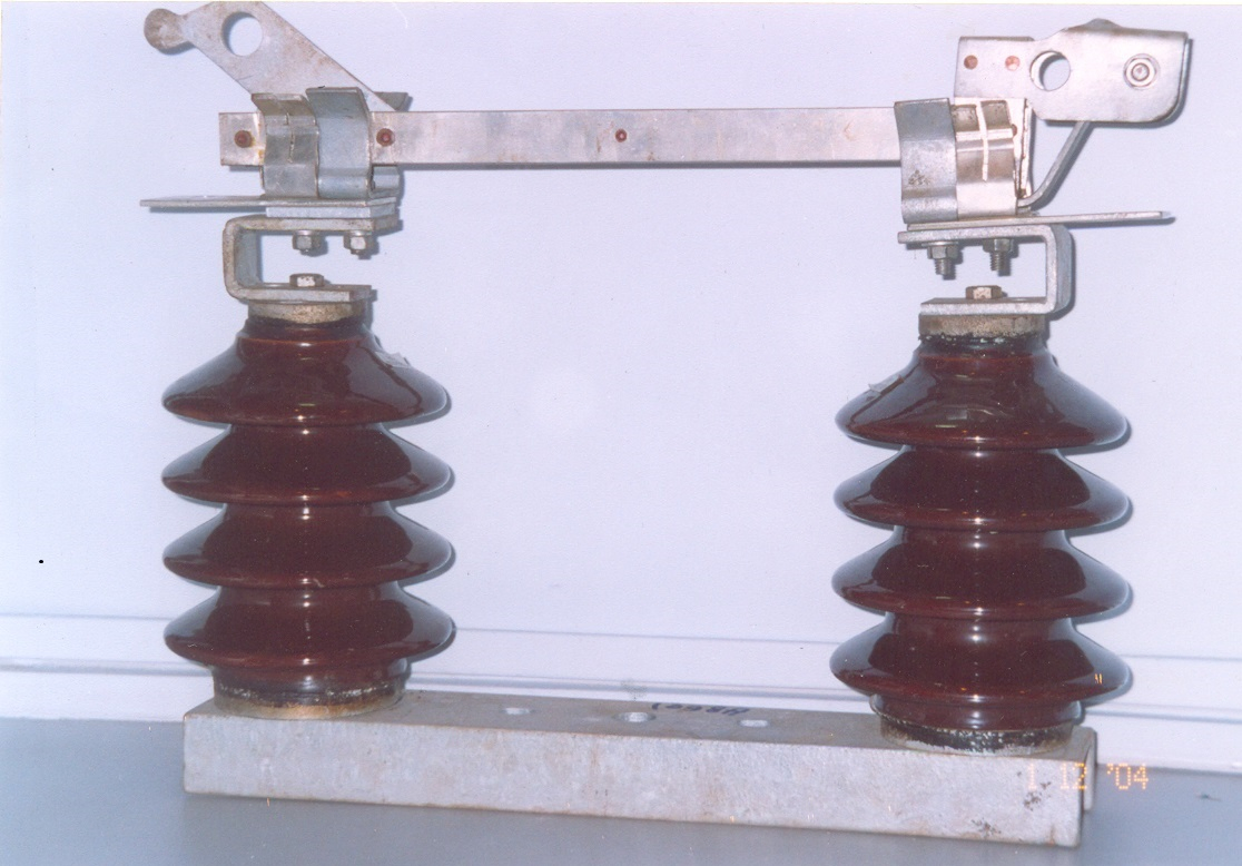
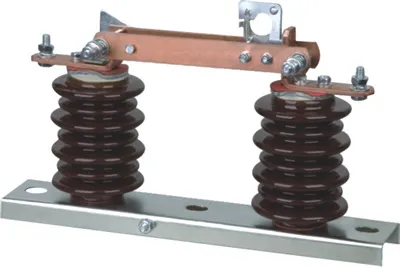
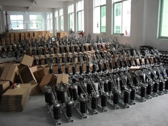
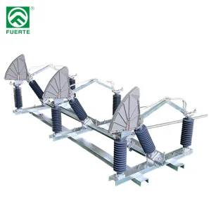
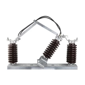
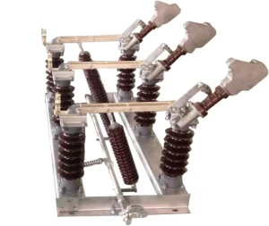
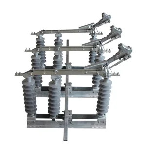
The isolating link shall be of the vertical opening, designed for single phase manual operation. It shall be easily removed and replaced by using a portable operating rod.
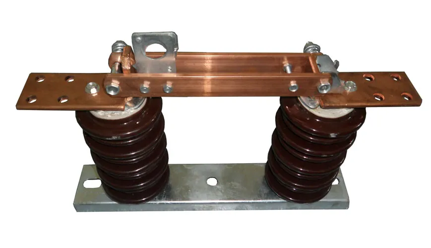
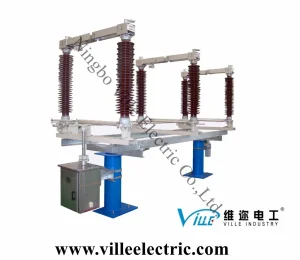
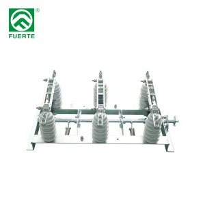
The isolating link shall incorporate double porcelain insulators to suit voltage requirements and mounted on hot dipped galvanised steel under base suitable for vertical mounting.
The isolating link shall be arranged so that each unit is mounted independently on an angle bracket. It shall be supplied complete with the angle bracket and accessories suitable for mounting on 'U' type steel channel. The drawings to be submitted shall indicate all the applicable mounting positions.
The isolator shall be designed such that in fully open position, it shall provide adequate electrical isolation between the contacts on each phase. It shall conform to the requirement as single point isolation for safety.
All steel parts shall be hot dip galvanized to BS 729. The minimum coating of galvanizing required is 80 microns.
The solid link shall be removable from the mounting by use of operating rod.
All current carrying parts of the isolator shall be made of high conductivity material.
The isolator shall be fitted with clamp connectors for Aluminium (ACSR) conductor of up to 18.2mm diameter.
RATINGS
The rating of the complete isolator shall be as follows:
Rated voltage: 36 kV
Rated frequency: 50 Hz
Rated lightning impulse withstand voltage: 200 kV
Rated power frequency withstand voltage, dry: 95 kV
Rated normal current: 400 Amps
Rated short time withstand current for 3 sec, min.: 18.0 kA
Minimum creepage distance of insulators: 900 mm
S.No
DESCRIPTION
UNITS
BIDDER OFFERED VALUE
1.
Rated Voltage
KV
12 KV
2.
Frequency
Hz
50 Hz
3.
Rated continuous current
A
630
4.
Impulse withstand voltage to ground
KV
95
5.
Impulse withstand voltage across gaps
KV
110
6.
Dry one-minute power frequency withstand voltage to ground
KV
35
7.
Dry one minute power frequency withstand voltage across gap
KV
45
8.
Wet one minute power frequency withstand voltage to ground
KV
30
9.
Limits of radio interference 10KV and 1000 K.C/Sec
250 uV
10.
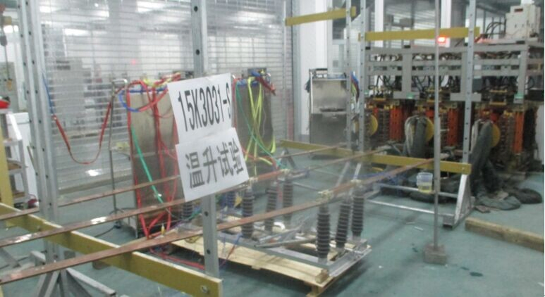
Temperature rise at rated current (max.)
30oC at 50oC ambient
11.
Dimensions and mechanical, Electrical values Of Polymer Insulator
12.
Leaking distance
mm
508 (minimum)
13.
Dry arcing distance
mm
210 (minimum)
14.
Cantilever strength
kg
400
15.
Tensile strength
kg
1000
16.
Compressive strength
kg
5400
17.
Tensile proof test load
kg
700
18.
Dry power frequency flashover
KV
85
19.
Wet power frequency flashover
KV
55
20.
Dry one-minute power frequency withstand
KV
70
21.
Wet one-minute power frequency withstand
KV
45
22.
Impulse flash over positive
KV
115
23.
Impulse flashover negative
KV
140
24.
Power frequency puncture voltage
KV
150
Frequently Asked Questions
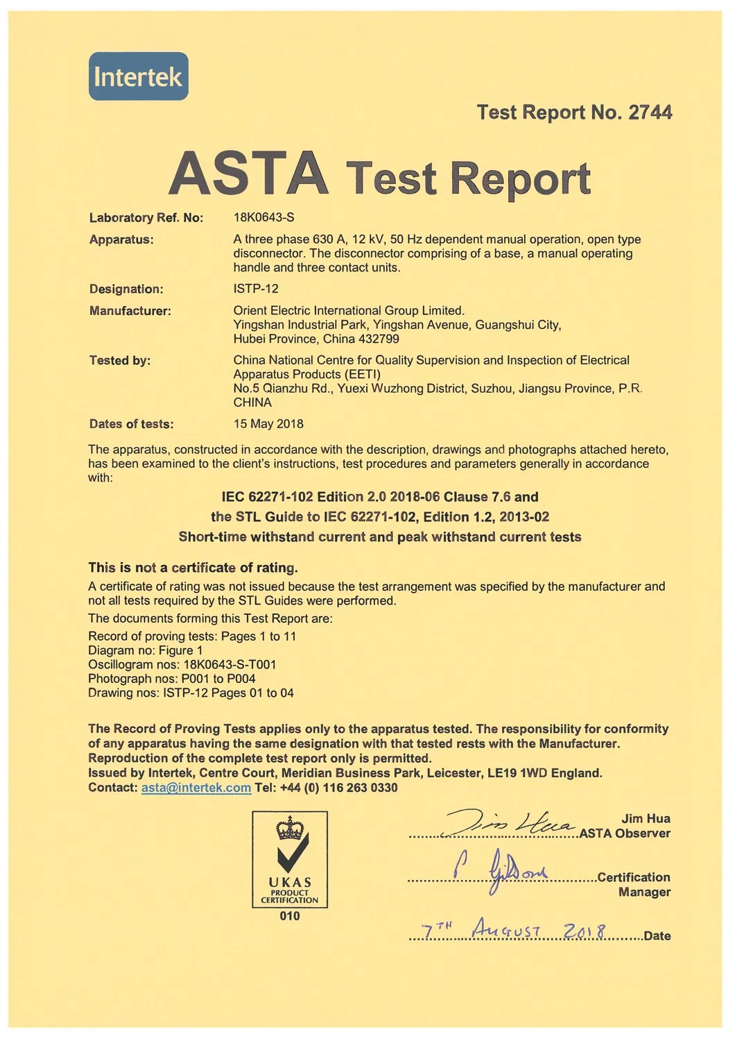
Q: What standard specifications does this isolator switch comply with?
A: The isolator switch complies with IEC 129:1975, IEC 60694:2002, IEC62271-102, and BS 729 for hot-dip galvanized coating, ensuring strict adherence to international safety and design criteria.
Q: What environmental conditions are suitable for this isolator?
A: It is designed for continuous outdoor operation in tropical areas with altitudes up to 2200m, humidity up to 90%, temperatures ranging from -1ºC to +40ºC, and severe coastal saline environments.
Q: How is the solid link isolator operated?
A: It features a vertical opening, single-phase manual operation design. The isolating link can be easily removed and replaced using a standard portable operating rod.
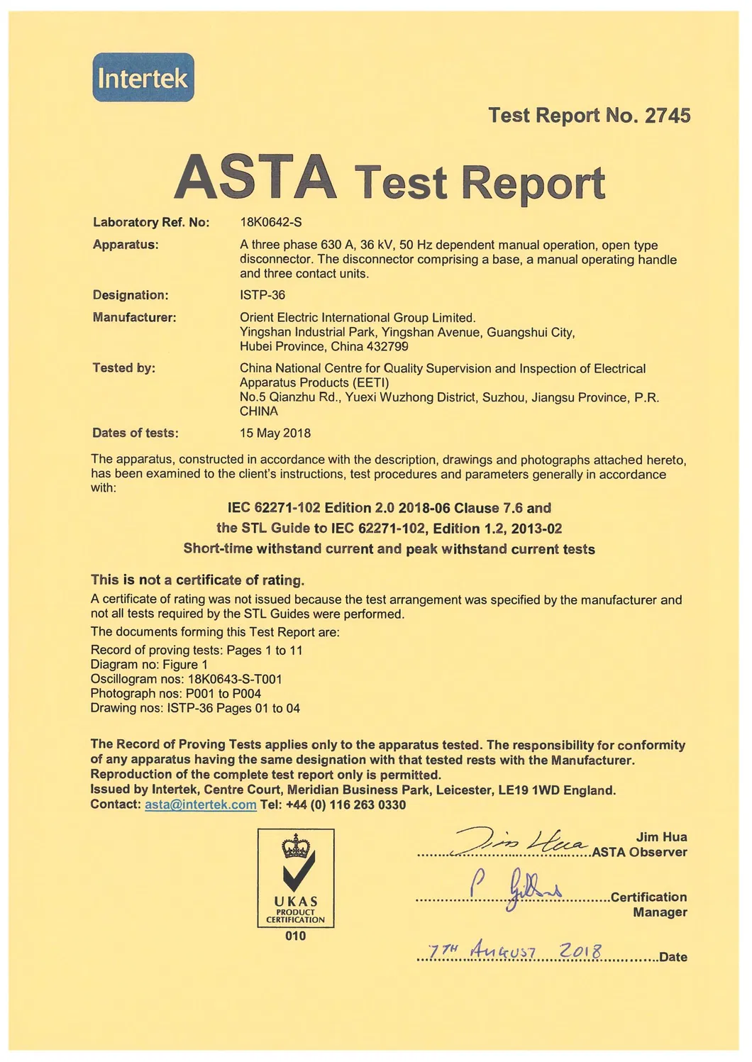
Q: What are the electrical parameters of the 36 kV rated model?
A: The 36 kV model features a rated normal current of 400 Amps, a rated lightning impulse withstand voltage of 200 kV, a dry power frequency withstand of 95 kV, and a minimum creepage distance of 900 mm.
Q: What conductor type and sizes can be connected to the isolator?
A: The isolator is fitted with heavy-duty clamp connectors suitable for securing Aluminium (ACSR) conductors with a diameter of up to 18.2mm.
Q: What is the quality and thickness of the galvanizing on the steel components?
A: All steel parts are hot-dip galvanized to BS 729 specifications, ensuring a durable protective coating with a minimum thickness of 80 microns to withstand corrosion.