1 / 2
| Setting Range of Thermal Trips (A) |
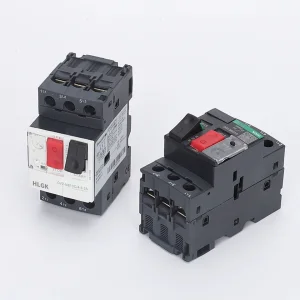
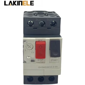
Maximum Horsepower Ratings | GV2ME Pushbutton |
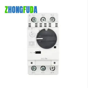
GV2P Rotary Handle |
|||||
|---|---|---|---|---|---|---|---|---|
| Single Phase | Three Phase | |||||||
| 115V (HP) |
230V (HP) |
200V (HP) |
230V (HP) |
460V (HP) |
575V (HP) |
Catalog Number | Catalog Number | |
| 0.11 - 0.16 0.016 - 0.25 0.25 - 0.40 0.40 - 0.63 0.63 - 1 1 - 1.6 1.6 - 2.5 2.5 - 4 4 - 6.3 6 - 10 9 - 14 13 - 18 17 - 23 20 - 25 24 - 32 |
– – – – – – – 1/8 1/4 1/2 3/4 1 1-1/2 2 2 |
– – – – – 1/10 1/6 1/3 1/2 1-1/2 2 3 3 3 5 |
– – – – – – 1/2 3/4 1-1/2 2 3 5 5 5 10 |
– – – – – – 1/2 1 1-1/2 3 3 5 7-1/2 7-1/2 10 |
– – – – 1/2 3/4 1 2 3 5 10 10 15 15 20 |
– – – – 1/2 1 1-1/2 3 5 7-1/2 10 15 20 20 30 |
GV2ME01 GV2ME02 GV2ME03 GV2ME04 GV2ME05 GV2ME06 GV2ME07 GV2ME08 GV2ME10 GV2ME14 GV2ME16 GV2ME20 GV2ME21 GV2ME22 GV2ME32 |
GV2P01 GV2P02 GV2P03 GV2P04 GV2P05 GV2P06 GV2P07 GV2P08 GV2P10 GV2P14 GV2P16 GV2P20 GV2P21 GV2P22 |
| 1 - 1.6 1.6 - 2.5 2.5 - 4 4 - 6 6 - 10 10 - 16 16 - 25 25 - 40 40 - 63 |
– – 1/8 1/4 1/2 1 2 3 5 |
1/10 1/16 1/3 1/2 1-1/2 2 3 7-1/2 10 |
– 1/2 3/4 1-1/2 2 3 5 10 20 |
– 1/2 1 1-1/2 3 5 7-1/2 10 20 |
3/4 1 2 3 5 10 15 30 40 |
1 1-1/2 3 - 7-1/2 10 20 30 60 |
GV3ME06 GV3ME07 GV3ME08 GV3ME10 GV3ME14 GV3ME20 GV3ME25 GV3ME40 GV3ME63 |
|
| Picture | Only one trip or fault signaling contact can be installed per GV2ME/GV3ME device | ||||
|---|---|---|---|---|---|
| Description | Characteristics | Voltage | Frequency | Catalog Number | |
|
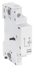
Voltage trips GV2 & GV3P |
Undervoltage or Shunt trip (external mounting, 1 block right side only) |
24 V | 50 Hz 60 Hz |
GVA•025 GVA•026 |
| 48 V | 50 Hz 60 Hz |
GVA•055 GVA•056 |
|||
| 100–110 V | 50/60 Hz | GVA•107 | |||
| 110–115 V | 50 Hz 60 Hz |
GVA•115 GVA•116 |
|||
| 120–127 V | 50 Hz | GVA•125 | |||
| 127 V | 60 Hz | GVA•115 | |||
| 200 V | 50 Hz | GVA•207 | |||
| 200–220 V | 60 Hz | GVA•207 | |||
| 220–240 V | 50 Hz 60 Hz |
GVA•225 GVA•226 |
|||
| 380–400 V | 50 Hz 60 Hz |
GVA•385 GVA•386 |
|||
| 415–440 V | 50 Hz | GVA•415 | |||
| 415 V | 60 Hz | GVA•416 | |||
| 440 V | 60 Hz | GVA•385 | |||
| 480 V | 60 Hz | GVA•415 | |||
| 500 V 600 V |
50 Hz 60 Hz |
GVA•505 | |||
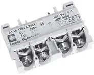
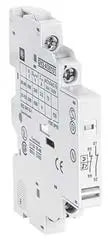
| Picture | Description | Mounting Location | Max. No. of Blocks | Contact Type | Catalog Number |
|---|---|---|---|---|---|
|
Instantaneous auxiliary contacts GV2ME + GV3P |
Frontbg | 1 | N.O. or N.C. N.O. + N.C. N.O. + N.O. |
GVAE1 GVAE11 GVAE20 |
| Left Hand Side | 2 | N.O. + N.C. N.O. + N.O. |
GVAN11 GVAN20 |
||
|
Fault signaling contact + instantaneous auxiliary contact GV2 + GV3P | Left Hand Side | 1 | N.O. (fault) + N.O. N.O. (fault) + N.C. N.C. (fault) + N.O. N.C. (fault) + N.C. |
GVAD1010 GVAD1001 GVAD0110 GVAD0101 |
| Short circuit signaling contact GV2 + GV3P |
Left Hand Side | 1 | SPDT | GVAM11 |
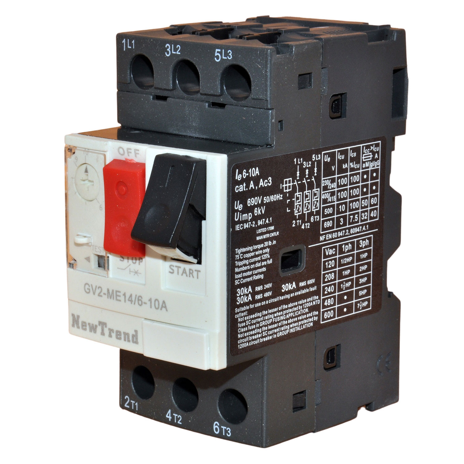
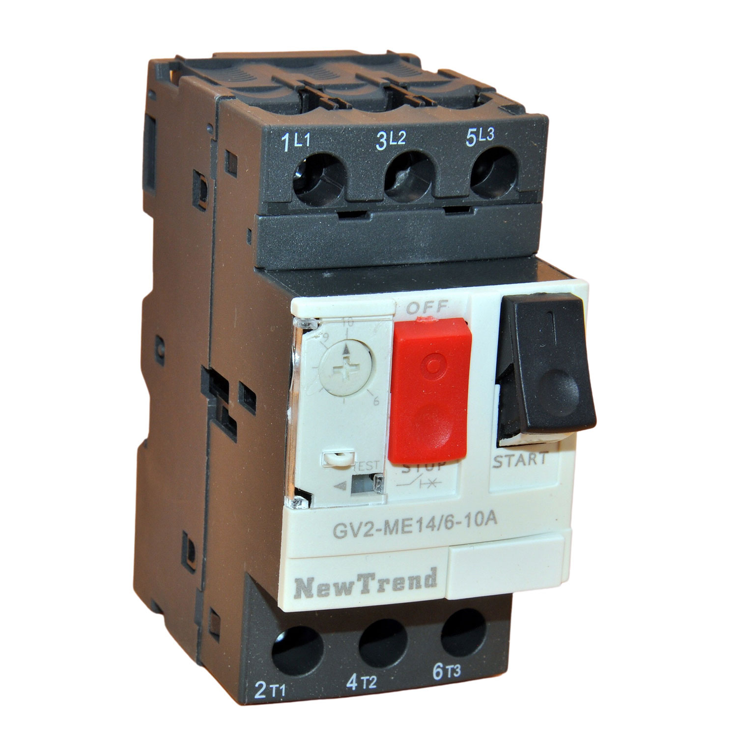
They are designed for overload and short circuit protection of motors in AC 50/60Hz networks, up to 660V, and current ratings of 0.1-80A. They serve as full-voltage starters to start and cut off motors under AC3 loads, and protect circuit and power equipment in distribution networks.
To order an undervoltage trip, replace the bullet (•) in the catalog number with a "U" (e.g., GVAU025). To order a shunt trip, replace the bullet (•) with an "S" (e.g., GVAS025).
Only one trip or fault signaling contact block can be installed per GV2ME/GV3ME device.
The GVAD block must always be mounted directly adjacent to the manual motor starter (left-hand side).
For spring terminal configurations, you need to add the number "3" to the end of the catalog number (for example, GVAE11 becomes GVAE113).
No, these auxiliary contact blocks and trips cannot be used in combination with the GV2GH7 insulator.