Bowser Electric
A main switch disconnector is more than a handle on a panel door. It is a defined isolation point, and its correct installation affects maintenance, fault response, and operator safety. This guide introduces how to wire a main switch disconnector for industrial panels, from checking device ratings and terminal markings to planning conductor routes and confirming specified tightening torque. Small details matter. A loose termination can heat under load; an unclear label can delay safe isolation.
Electrical educator Mike Holt’s safety-first teaching can be paraphrased this way: “A diagram is not proof of isolation; verify the circuit before touching it.” This is a paraphrase, not a verbatim quotation. The advice is practical: identify every supply, isolate the panel, and verify the absence of voltage with suitable test equipment. Follow the device manufacturer’s instructions, the panel design, and applicable local requirements. A disconnector’s presence alone does not prove that every energy source has been isolated.
The sections ahead explain how to prepare, connect, inspect, and document the installation. Expect details such as terminal labels, conductor size, protective devices, enclosure clearances, and torque values. These are not interchangeable across models. Some steps may seem repetitive. Keep them. If the drawings, device markings, or site conditions disagree, stop and resolve the mismatch with a qualified electrical professional before energizing the panel.
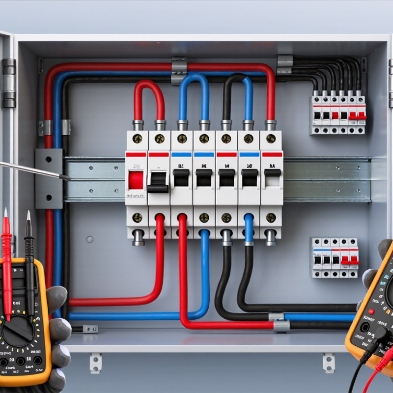
How to Wire a Main Switch Disconnector for Panels in 2026?
A main switch disconnector provides a clear way to isolate a panel’s incoming supply for maintenance. In the ON position, it connects the supply to the panel’s distribution system. In the OFF position, it separates them, helping prevent power from reaching downstream circuits. It is not automatically an overload or short-circuit protective device; that function depends on the panel’s other protective equipment.
Its rating, pole arrangement, and position must suit the supply and panel design. A qualified electrician should check the manufacturer’s diagram, conductor sizes, terminal markings, and required upstream protection before making connections. They should isolate the supply and verify the absence of voltage with appropriate test equipment. Details vary between installations. A tidy diagram can still be misunderstood, and I have seen that simple assumption cause confusion.
Tips: Label the incoming supply and outgoing panel conductors clearly. Keep the disconnector accessible, and confirm its OFF position before servicing. Never rely on the handle alone as proof of isolation; test and follow the site’s safety procedure.
| Panel Topic | What to Know | Design or Verification Point |
|---|---|---|
| Main function | A main switch disconnector provides a means to manually isolate a panel or circuit from its electrical supply. It does not necessarily provide overload or short-circuit protection. | Confirm that separate protective devices are provided where required by the panel design and applicable electrical rules. |
| Device selection | Select a device suitable for the system voltage, number of poles, rated current, utilization category, enclosure conditions, and expected short-circuit coordination. | Check the device nameplate, technical documentation, and panel design calculations; do not size it by current alone. |
| Pole arrangement | Common arrangements include single-pole, double-pole, three-pole, and four-pole devices. The appropriate arrangement depends on the supply system and isolation requirements. | Determine whether the neutral must be switched under the applicable rules and design. Never assume neutral switching is required or permitted in every system. |
| Terminal identification | Terminals are identified by markings or a connection diagram. Many devices distinguish supply-side line terminals from load-side terminals, but marking conventions vary. | Use the exact terminal markings and wiring diagram supplied with the selected device; do not rely on physical position alone. |
| Connection overview | At a functional level, the incoming supply connects to the designated line terminals, and the panel circuits connect to the designated load terminals, following the device diagram. | Conductor type, cross-section, preparation, routing, and terminal tightening must match the device instructions and the approved panel design. |
| Protective earth | Protective-earth conductors are connected to the panel’s protective-earth bar and are not routed through an ordinary switch disconnector. | Maintain the required protective bonding and earth continuity in accordance with the panel design and local regulations. |
| Isolation and labeling | The operating handle should clearly indicate the switch position, and the device should be identified as the panel’s main isolating switch where applicable. | Check that the device is accessible, correctly mounted, and labeled consistently with the panel drawings and site isolation procedure. |
| Pre-energization checks | Inspection and testing should confirm correct connections, secure terminals, suitable clearances, protective bonding, and operation of the switching mechanism. | Testing must be performed by a qualified person using appropriate procedures and instruments before the panel is energized. |
| Standards and safety | Switch-disconnector requirements are addressed by standards such as IEC 60947-3; panel assemblies and installation rules may also be subject to other standards and local codes. | Use the current standards adopted in the installation’s jurisdiction. Installation work should be carried out by a licensed or otherwise qualified electrician. |
Safety note: This table is a general design overview, not a wiring procedure. Electrical panels can contain lethal voltages. Isolate all sources, verify absence of voltage with an appropriate tester, and follow applicable regulations and device instructions.
It isolates the panel from its incoming supply. In the ON position, it feeds downstream circuits. In the OFF position, it separates them.
Not usually. Separate protective equipment must handle overloads and short circuits. Check the panel design and upstream protection.
A qualified electrician should perform the work. They must check ratings, conductor sizes, terminal markings, and installation requirements.
Identify every possible supply source. This may include utility power, a generator, or backup equipment. Isolate each source properly.
No. The handle alone is not proof of isolation. Lock the isolation point, attach a warning tag, and test for voltage.
Inspect a suitable tester first. Prove it on a known live source, test all relevant conductors, then prove it again.
Terminal positions may differ between devices. Do not assume line and load terminals are interchangeable. Follow the diagram for neutral switching.
Leave enough enclosure space. Avoid sharp cable bends and conductor strain. Use the specified preparation method and tightening torque.
A qualified electrician should inspect the completed wiring. Record the device rating and inspection results. A tidy panel can still be wrong.
Missing a secondary supply is possible, even for experienced workers. Pause, review the diagram, and confirm the isolation boundary. No shortcuts.
This guide explains how to wire a main switch disconnector for industrial panels by outlining the key stages of a safe, well-documented installation. It begins with the disconnector’s role in isolating a panel and the importance of selecting equipment with ratings suited to the system. Before work starts, the installer should review the device’s wiring diagram, confirm compatibility with the panel, and check applicable electrical requirements.
The process also emphasizes isolating the supply and verifying that the panel is de-energized before installation. Connections should follow the manufacturer’s diagram and be completed by a qualified professional using appropriate procedures and protective equipment. After installation, inspect the connections, perform suitable tests, and record the results. Careful planning, verification, and documentation help support reliable operation and make future maintenance clearer.