Bowser Electric
Electrical safety begins with a precise question: what is the safe leakage current limit for rccb protection? The answer is not one universal number. It depends on the RCCB’s rated residual operating current, installation design, equipment condition, and local electrical requirements.
For personal protection, 30 mA RCCBs are widely used in many residential and commercial circuits. They are designed to disconnect power when leakage reaches a dangerous level. A 100 mA or 300 mA device may support fire protection or larger installations, but it may not provide the same level of protection against electric shock. The rating matters.
Small details can change the risk. Imagine a damp bathroom, a damaged cable, or a metal appliance with a weak earth connection. Leakage may rise quickly. An RCCB can detect imbalance between live and neutral conductors, but it does not replace proper grounding, insulation testing, or overload protection. It also cannot guarantee safety after every fault.
This 2026 guide explains practical leakage limits, RCCB sensitivity ratings, nuisance tripping, and correct testing methods. It separates technical recommendations from assumptions. Standards such as IEC 61008 and IEC 61009 provide useful reference points, while local rules may differ. Always verify the device marking and installation requirements.
Some advice online is too confident. That deserves caution. A 30 mA rating does not mean 30 mA is harmless. It describes the trip threshold, not a safe exposure level for the human body. Regular testing, professional inspection, and accurate circuit measurement remain essential. A qualified electrician should confirm the final selection before energizing the installation.
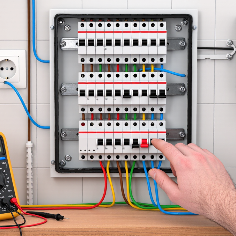
An RCCB monitors the current leaving through the live conductor and returning through the neutral conductor. Under normal conditions, these currents are nearly equal. When electricity escapes through damaged insulation, a damp surface, or a person, the balance changes. The RCCB detects this residual current and disconnects the circuit. It does not replace overcurrent protection, because it cannot reliably detect overloads or short circuits between conductors.
A 30 mA setting is common for additional protection in many residential circuits. It is not a universal safe limit. Higher settings, such as 100 mA or 300 mA, may support equipment protection or fire-risk coordination. They may not provide the same level of personal protection. Selection depends on earthing arrangements, circuit design, connected equipment, and local electrical requirements. The label’s rated residual operating current is a reference value, not permission to ignore smaller leakage.
Consider a washing machine in a humid utility room. Its internal filter may create normal leakage, while damaged insulation can add more. Several small leaks can combine and nuisance-trip one RCCB. A qualified electrician can measure circuit leakage, inspect insulation, and confirm disconnection performance with calibrated equipment. Pressing the test button checks the mechanism, but it does not prove every safety condition. That distinction is easy to miss. I would also question any installation that repeatedly resets without finding the cause. Fresh wiring is not automatically safe; moisture, aging, and poor connections can change the result.
An RCCB trip rating defines the residual current that can make the device disconnect. It is not a permission slip for continuous leakage. A 30 mA RCCB is commonly selected for additional protection against electric shock. When measured leakage approaches this value, nuisance trips may occur before the rated threshold is reached.
In a practical inspection, I measure the circuit with appliances connected and disconnected. A damp outdoor socket, damaged cable, or several filter capacitors can raise the combined leakage. Small currents add together. That detail is often missed.
A 100 mA or 300 mA RCCB may suit upstream protection or fire-risk control, depending on the installation design. These ratings should not replace 30 mA protection for circuits requiring stronger personal protection. Selectivity also matters. An upstream device with a higher rating or intentional delay can prevent every circuit from shutting down during one fault.
The acceptable limit depends on local rules, equipment type, earthing arrangements, and manufacturer instructions. IEC-based requirements provide useful technical guidance, but they do not remove the need for site verification. A qualified electrician should test trip time, operating current, insulation resistance, and protective conductor continuity.
Be careful with simple numbers. A circuit reading 28 mA is not automatically safe because it sits below 30 mA. Conditions can change with moisture, temperature, and connected loads. In my experience, unexplained repeated tripping deserves investigation, not a larger RCCB. Sometimes the measurement itself is wrong. That possibility deserves attention.
Start with the circuit’s real operating voltage, frequency, insulation, cable length, and connected equipment. A useful estimate is Iₗₑₐₖ ≈ V/R + 2πfCV . The first term represents resistive leakage. The second represents capacitive leakage from filters and cable capacitance.
For example, IEC 60364-6:2016 specifies 1 MΩ as a minimum insulation-resistance value for many low-voltage circuits tested at 500 V DC. At 230 V, V/R equals 0.23 mA. That figure is only a test-based reference, not the complete operating leakage. One 1 nF capacitance to earth at 50 Hz adds about 0.072 mA. Four similar devices could add approximately 0.29 mA.
Add every branch current, including power supplies, lighting controls, motors, and long cables. Field calculations often keep normal leakage below one-third of an RCCB’s rated residual current. For a 30 mA RCCB, that suggests a planning target below 10 mA. This is a practical margin, not a universal legal limit. IEC 61008-1 defines performance requirements for residential RCCBs, including their rated residual operating current, but installation conditions still matter.
Measure the circuit with a leakage-current clamp after energising all loads. Compare the reading with the calculated value. Unexpected differences deserve investigation. Harmonic currents, moisture, damaged insulation, and filter aging can distort a simple estimate. The formula helps, but it is not perfect. Test results remain essential.
RCCB sensitivity must match the application, not simply the highest protection level. IEC 60364-4-41 identifies 30 mA residual-current protection as additional protection against electric shock in many final circuits. IEC 61008-1 covers RCCBs for household and similar installations. However, 30 mA is not a universal “safe leakage current limit.” The actual risk depends on current path, exposure time, moisture, and human health.
For bedrooms, bathrooms, kitchens, outdoor sockets, and portable equipment, a 30 mA RCCB is commonly selected. It can disconnect a dangerous fault quickly, especially where wet skin reduces body resistance. A 10 mA device offers higher sensitivity, but nuisance tripping may increase. It suits limited circuits, medical environments, or locations requiring closer supervision. Larger systems often use 100 mA or 300 mA devices for equipment and fire-risk protection. These ratings should not replace 30 mA personnel protection downstream. IEC TS 60479-1 shows that shock effects depend strongly on duration and current path. Small numbers can still be serious.
Tips: Measure normal leakage before choosing sensitivity. Use a leakage clamp meter, then allow practical operating margin. Variable-speed drives, filters, and long cables may create standing leakage. Select the RCCB type according to the load waveform and manufacturer data. Do not treat a 30 mA trip rating as a guaranteed survival threshold. Testing matters. Press the test button regularly, record trip times, and investigate repeated trips instead of simply resetting the device. In real installations, perfect coordination is difficult—and assumptions deserve review.
Typical RCCB residual operating-current selections by application
RCCB sensitivity is the rated residual operating current (IΔn), not a universal “safe leakage current limit.” A 30 mA RCCB is commonly used for additional protection against electric shock, while 100–500 mA devices are generally selected for upstream, fire-protection, equipment-leakage, or selectivity requirements. Final selection must follow local electrical regulations, earthing arrangements, load leakage, and coordination with upstream and downstream protective devices.
Testing RCCB Protection and Troubleshooting Repeated Trips
A 30 mA RCCB is commonly used for additional personal protection. It is not a “safe leakage limit.” IEC 61008-1 requires operation at its rated residual current within a defined time. Normal appliance leakage should remain far below that threshold. NFPA’s Home Electrical Fires report estimated 34,700 residential electrical fires annually between 2015 and 2019. These fires caused about 470 deaths and 1,100 injuries.
Press the RCCB test button regularly. The power should disconnect immediately. This confirms the mechanism works, but it does not measure trip current or trip time. For a proper check, an electrician uses a calibrated RCD tester. The test should record half-rated current, rated current, and five-times-rated current. Write down the results. Memory is unreliable.
Repeated trips need a controlled search. Unplug portable appliances, reset the RCCB, then reconnect devices one at a time. Inspect damp sockets, outdoor cables, heating elements, and extension leads. A trip after rain suggests moisture, not a faulty RCCB. Simultaneous leakage from several filters can also exceed 30 mA. Do not keep resetting it. Isolation testing may reveal damaged insulation, but live troubleshooting is dangerous and requires suitable competence. A loose neutral can create confusing symptoms. I have seen “nuisance” trips disappear after one appliance was removed, but that diagnosis was only confirmed by measured results. NFPA data shows why guessing is a poor maintenance method.
| Dimension | Typical Value or Criterion | Practical Guidance | Important Notes |
|---|---|---|---|
| RCCB function | Residual-current protection | An RCCB compares the current flowing through the live conductors with the current returning through them. A difference indicates current escaping to earth or another unintended path. | An RCCB normally does not provide overload or short-circuit protection. An appropriately rated overcurrent protective device is generally required separately. |
| Common rated residual operating current, IΔn | 10 mA, 30 mA, 100 mA, 300 mA | Select the value according to the installation design, earthing arrangement, equipment characteristics, and applicable electrical regulations. | The marking IΔn is the residual current at which the RCCB is designed to operate under its specified conditions. It is not a general “safe leakage current” for every person or installation. |
| Additional protection for people | 30 mA RCCB commonly used | A 30 mA device is widely specified for additional protection in locations and circuits identified by installation standards, such as many socket-outlet and wet-area circuits. | A 30 mA rating does not make electric shock safe and does not replace basic insulation, protective earthing, bonding, correct disconnection, or safe work practices. |
| Safe leakage-current interpretation | No universal safe limit | Treat persistent or rising leakage as a fault or a design issue until assessed. Use the RCCB rating, circuit design, equipment instructions, and local code as the decision basis. | Shock risk depends on current path, duration, body impedance, environment, and waveform. Even currents below an RCCB operating threshold can be hazardous. |
| Recommended operating margin | Keep normal leakage well below IΔn | As an engineering rule of thumb, keep the expected steady-state leakage of a circuit comfortably below the RCCB threshold; approximately 30% of IΔn is often used as a planning target where applicable. | This is a design guideline, not a universal statutory limit. Variable-speed drives, filters, LED drivers, UPS systems, and heating equipment may produce normal high-frequency or capacitive leakage. |
| Example: 30 mA RCCB planning value | About 9 mA planning target | Estimate or measure the combined normal leakage: 0.30 × 30 mA ≈ 9 mA Investigate the circuit if the steady-state value approaches the device threshold or causes nuisance operation. | The 9 mA value is a margin guideline, not a guaranteed trip point or a statement that 9 mA is safe to touch. |
| Pre-test safety | De-energize where possible | Identify the circuit, isolate energy sources, prevent automatic restart, use suitable PPE and test instruments, and verify the absence of voltage before opening an enclosure. | Testing and fault-finding should be performed by a competent person. Do not bypass, lock on, or remove an RCCB to keep equipment running. |
| RCCB TEST button | Should trip the device | With the installation energized and safe to test, press the built-in TEST button. The RCCB should trip and disconnect the protected circuit; reset it only after confirming conditions are safe. | The button checks the internal trip mechanism and test circuit. It does not measure actual residual current, trip time, earth resistance, or complete installation safety. |
| Instrument trip test at 0.5 × IΔn | Normally should not trip | For a standard non-delayed RCCB, a test at half the marked residual operating current is commonly used to confirm that unwanted tripping does not occur below the applicable operating range. | Follow the tester procedure and the product and installation standard. Device type, waveform, frequency, selectivity, and time delay affect the result. |
| Instrument trip test at 1 × IΔn | Must trip within the applicable time | For many instantaneous RCCBs, a 1 × IΔn test is commonly checked against a maximum disconnection time of 300 ms, subject to the applicable product standard and device type. | Always compare the measured result with the manufacturer’s marking, certification data, and the local verification requirements. |
| Instrument trip test at 5 × IΔn | Fast-trip verification | For many instantaneous 30 mA RCCBs, a 5 × IΔn test is commonly checked against a maximum trip time of 40 ms. | Do not apply this criterion indiscriminately to selective, time-delayed, portable, or special-purpose devices. Confirm the correct test mode before testing. |
| Type and waveform selection | AC, A, F, or B as designed | Use a tester and RCCB type suitable for the expected residual-current waveform. Type A, F, and B devices address different combinations of pulsating DC, mixed-frequency, or smooth DC residual current. | A test using the wrong waveform or an incompatible instrument can produce misleading results. The device marking and circuit load determine the correct selection. |
| Repeated trip: immediate trip on reset | Likely active fault or wiring issue | Switch off downstream circuits or unplug loads, reset the RCCB, and re-energize circuits one at a time. Inspect the identified circuit for damaged insulation, moisture, neutral-earth contact, or incorrect neutral routing. | Do not repeatedly reset a device that trips immediately. Persistent tripping requires isolation and diagnosis, not substitution with a higher-rated RCCB. |
| Repeated trip: delayed or intermittent | Cumulative or changing leakage | Measure circuit leakage under normal operating conditions and during equipment start-up. Check heating elements, pumps, motors, outdoor wiring, filters, surge protective devices, and moisture-related insulation deterioration. | Several small leakage currents can add together. Temperature, humidity, switching events, and electronic power supplies can make the problem intermittent. |
| Neutral-to-earth connection downstream | Common trip cause | Check for accidental neutral-earth contact after the RCCB, shared neutrals between RCCB-protected circuits, crossed neutrals, and borrowed neutrals. Correct the wiring only after isolation and verification. | A neutral-earth connection downstream can divert return current outside the RCCB sensing path and create an apparent residual current. |
| Leakage-current measurement | Use a suitable leakage clamp meter | Clamp around all live conductors belonging to the same circuit together. The meter then reads the imbalance current. Clamping only one conductor measures load current, not residual current. | Use an instrument rated for the system voltage, conductor arrangement, and expected frequency range. Avoid disturbing conductors unnecessarily. |
| Insulation resistance test | Test only isolated equipment | After disconnecting sensitive electronic equipment, surge protective devices, control systems, and other items that could be damaged, test insulation according to the applicable installation procedure. | A high insulation-resistance result does not rule out every operating leakage or electronic filter current. Reconnect equipment and assess the complete circuit appropriately. |
| RCCB will not reset | Possible fault, supply, or mechanism problem | Confirm the reset position, isolate downstream loads, check for a continuing residual fault, and verify supply conditions. If it still will not reset after the fault is removed, arrange competent inspection or replacement. | Never force the handle or defeat the trip mechanism. An RCCB can also fail mechanically or electrically and should be verified with appropriate testing. |
| Recordkeeping | Document every result | Record device type, IΔn, test waveform, test multiplier, trip time, leakage under load, circuit identification, environmental conditions, and corrective actions. | Trend measurements over time. A gradual increase in leakage can reveal insulation or equipment deterioration before nuisance trips become frequent. |
| Replacement decision | Match the design, not just the current rating | Replace only after identifying the cause where possible. Match poles, rated voltage, rated current, IΔn, RCCB type, time delay, short-circuit coordination, enclosure requirements, and local compliance needs. | Changing from 30 mA to a higher residual-current setting may reduce nuisance trips but can remove required additional protection and increase shock risk. |
It compares current leaving through live and returning through neutral. An imbalance indicates leakage. The device then disconnects the circuit.
Damaged insulation, damp surfaces, aging cables, and connected equipment can create leakage. Small currents may combine. Moisture matters.
No. It does not reliably detect overloads or conductor-to-conductor short circuits. Separate overcurrent protection remains necessary.
A 30 mA setting often provides additional shock protection in residential circuits. It is not a universal guarantee of safety.
No. A 28 mA reading is not automatically safe. Moisture, temperature, and added appliances can increase leakage later.
Its internal filter may create normal leakage. Damaged insulation or a humid room can add more current.
A qualified electrician should measure leakage with appliances connected and disconnected. They should inspect insulation and protective conductor continuity.
No. The button checks the RCCB mechanism only. It does not confirm trip time, insulation condition, or every protective connection.
These ratings may support upstream protection or fire-risk coordination. They may not provide the same personal protection as 30 mA.
Not automatically. The fault may remain hidden. I would investigate the cause first, although measurements can sometimes be imperfect.
This guide explains what an RCCB detects and why leakage current matters for electrical safety. An RCCB monitors the balance between current flowing through live conductors and returning through the circuit. If part of the current escapes to earth, the device can disconnect the supply before the leakage creates a serious shock or fire risk. The question “what is the safe leakage current limit for rccb” does not have one universal answer: common trip ratings include 30 mA for personal protection, while higher ratings may be used for equipment or upstream protection.
The article also shows how to estimate a circuit’s normal leakage by considering connected appliances, cable length, filters, insulation condition, and moisture. Selecting the correct sensitivity requires balancing protection with the possibility of nuisance tripping. Regular testing with the device’s test button, inspection of wiring, and step-by-step isolation of loads can help confirm reliable operation and identify repeated-trip causes. Actual installation and testing should be performed by a qualified electrical professional.