Bowser Electric
Residual current circuit breakers protect people and buildings by disconnecting power when leakage leaves the intended circuit path. Yet an unexpected trip can signal anything from a damp socket to deteriorating insulation. Understanding what causes a residual current circuit breaker to trip requires more than resetting the switch.
This 2026 diagnostic guide follows principles from IEC 60364-4-41, which addresses protection against electric shock, and IEC 61008-1 and IEC 61009-1, which define requirements for residual current devices. These standards support a practical distinction between protective operation and equipment failure. Electrical Safety First reports that defective appliances, damaged cables, and unsafe installations remain recurring sources of domestic electrical risk. The U.S. Consumer Product Safety Commission also continues to identify electrical malfunctions as a significant contributor to residential fire incidents.
Look for evidence, not guesses.
A trip that occurs when a washing machine starts may indicate appliance leakage, while a trip during rainfall may suggest moisture entering an outdoor circuit. Repeated trips deserve isolation testing by a competent electrician. Do not replace the breaker with a higher-rated device or bypass its protection. That decision can hide a dangerous fault.
The guide will examine nuisance tripping, neutral-to-earth faults, overload confusion, insulation breakdown, and cumulative leakage from multiple devices. It will also explain safe testing methods, visible warning signs, and when professional test instruments are necessary. No diagnosis process is perfect. Human assumptions can mislead, especially when faults appear intermittently. Reliable troubleshooting records the time, connected equipment, weather conditions, and reset behavior before drawing conclusions.
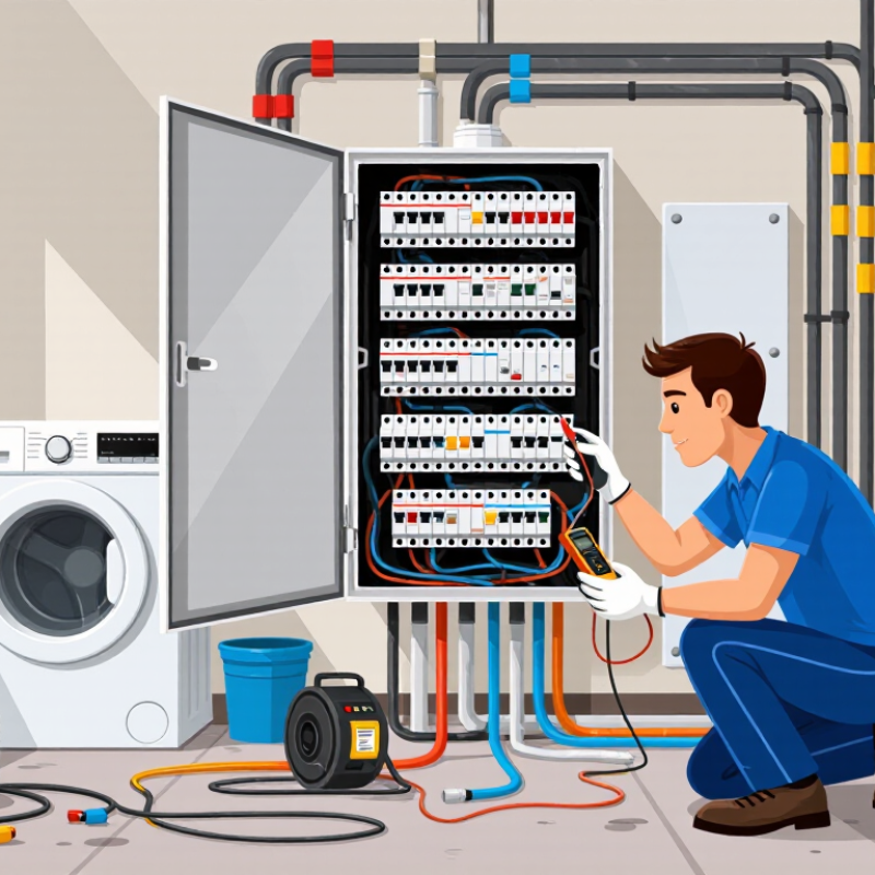
2026 How to Diagnose Residual Current Circuit Breaker Trips?
When an RCCB trips, identify its sensing type before replacing it. Type AC detects sinusoidal alternating leakage. Type A also responds to pulsating direct current from electronic loads. Type F and Type B suit more complex equipment and smooth DC risks. Check the marking carefully. The wrong type can trip unexpectedly or fail to detect the intended waveform.
Confirm the IΔn rating next. A 30 mA device commonly protects final circuits, while 100 mA or 300 mA ratings may support coordination or fire-risk control. Under IEC 61008, an RCCB should not trip at 0.5 IΔn. It must trip at IΔn within the specified time, commonly up to 300 milliseconds for standard devices. At higher test currents, limits become shorter, often 150 milliseconds at 2 IΔn and 40 milliseconds at 5 IΔn. IEC 61009 applies to RCBOs, which combine residual-current and overcurrent protection. Selective or delayed devices require different limits.
Tips: Isolate downstream circuits, then reconnect them one at a time. Use a calibrated tester at the device terminals. The test button checks operation, not full timing performance. In field inspections, nuisance trips often come from combined leakage in filters, heaters, or damp cables. I once blamed the RCCB too quickly. The insulation test later found a damaged cable. Record the waveform type, IΔn value, trip time, and circuit load before deciding.
A practical diagnostic data table for identifying RCCB characteristics, checking residual-current conditions, and comparing measured trip results with the general limits specified by IEC 61008-1 and IEC 61009-1.
| Diagnostic Dimension | Typical Value or Classification | What It Means | Recommended Check | Interpretation of Results | Reference |
|---|---|---|---|---|---|
| RCCB function | Residual-current protection | Detects an imbalance between the currents flowing in the live conductors and disconnects the circuit when the residual current reaches the operating threshold. | Confirm that the device is an RCCB or RCBO and verify the wiring, neutral path, pole configuration, and test-button operation. | An RCCB does not provide overload or short-circuit protection unless coordinated with a separate overcurrent protective device. | IEC 61008 / IEC 61009 |
| RCCB type | Type AC | Designed for sinusoidal alternating residual current. | Use only where the connected load is not expected to produce pulsating DC or smooth DC residual components. | Unexpected tripping or failure to trip may occur if electronic loads generate residual-current waveforms outside the device capability. | IEC 61008-1 / 61009-1 |
| RCCB type | Type A | Detects sinusoidal AC residual current and pulsating DC residual current. | Consider this type for single-phase electronic equipment, power supplies, LED drivers, induction appliances, and household appliances with rectifier inputs. | Usually more suitable than Type AC when the load contains single-phase electronic rectification. | IEC 61008-1 / 61009-1 |
| RCCB type | Type F | Provides Type A functions and is intended for certain mixed-frequency residual currents produced by single-phase variable-speed equipment. | Check the appliance documentation and the required frequency range before selecting this type. | Useful where a conventional Type A device may not provide the required response to mixed-frequency leakage. | IEC 62423 |
| RCCB type | Type B | Designed for AC, pulsating DC, and smooth DC residual-current components within its specified operating range. | Consider for three-phase converters, photovoltaic inverters, electric-vehicle charging equipment, variable-speed drives, and medical or industrial power electronics where smooth DC leakage is possible. | Use only after confirming the equipment leakage waveform and the installation design requirements. | IEC 62423 |
| Rated residual operating current, IΔn | 10 mA, 30 mA, 100 mA, 300 mA, or 500 mA | The marked residual current at which the RCCB is required to operate under its specified test conditions. | Read the nameplate and compare it with the circuit purpose, touch-protection requirements, leakage-current profile, and local installation rules. | A lower IΔn generally provides greater sensitivity but can increase nuisance tripping when normal leakage is high. | IEC 61008-1 / 61009-1 |
| Non-operating reference level | 0.5 × IΔn | The RCCB should not trip at or below half of its rated residual operating current during the applicable standard test. | For a 30 mA device, use 15 mA as the basic non-trip reference; for a 100 mA device, use 50 mA. | Tripping below this level can indicate cumulative leakage, transient leakage, incorrect testing, wiring problems, or a defective device. | IEC 61008-1 / 61009-1 |
| General instantaneous trip limit | ≤ IΔn | A general, non-time-delayed RCCB is required to trip when the residual current reaches its rated operating current under the applicable test waveform. | Test with a calibrated residual-current tester using the waveform appropriate to the RCCB type. | If the device does not trip at IΔn, investigate the tester, wiring, supply conditions, RCCB type, and device condition. | IEC 61008-1 / 61009-1 |
| Maximum trip time at IΔn | ≤ 300 ms for general type | The maximum operating time generally applied to a non-selective RCCB at its rated residual operating current. | Record both the measured residual current and trip time. Repeat the test according to the instrument and installation procedure. | A trip time above the applicable limit requires further investigation and may indicate a defective or unsuitable device. | IEC 61008-1 / 61009-1 |
| Maximum trip time at 2IΔn | ≤ 150 ms for general type | The expected maximum operating time at twice the rated residual operating current. | For a 30 mA RCCB, the nominal test current is 60 mA. Confirm that the tester applies the correct waveform and phase angle. | Results should be compared with the device category and the tester’s stated uncertainty. | IEC 61008-1 / 61009-1 |
| Maximum trip time at 5IΔn | ≤ 40 ms for general type | The expected maximum operating time at five times the rated residual operating current. | For a 30 mA RCCB, the nominal test current is 150 mA. Use this test only when permitted by the equipment and installation procedure. | A slow result can indicate mechanical wear, contamination, an incorrect test waveform, or a failing RCCB. | IEC 61008-1 / 61009-1 |
| Selective or time-delayed type | Type S | Includes an intentional time delay to achieve discrimination with downstream RCCBs. | Verify the S marking, upstream/downstream coordination, manufacturer time-delay data, and required test sequence. | Do not compare a Type S device directly with the instantaneous limits of a general-type RCCB. | IEC 61008-1 / 61009-1 |
| Unwanted tripping source | Normal protective-conductor leakage | Electronic filters, surge protection components, heating elements, and long cable runs can produce standing leakage. | Measure leakage with all loads connected, then isolate circuits or loads one at a time. Check neutral-to-earth connections downstream of the RCCB. | Persistent leakage approaching the device threshold can cause nuisance trips even when insulation resistance is acceptable. | Installation practice |
| Unwanted tripping source | Transient or switching leakage | Inrush current, motor starting, capacitor charging, lightning, and switching power supplies can create short-duration residual currents. | Use a suitable leakage-current logger or power-quality instrument where intermittent trips cannot be reproduced by a standard trip test. | Transient events may require load sequencing, surge protection review, or a correctly selected RCCB type rather than a higher IΔn rating. | Installation practice |
| Neutral conductor error | Shared, crossed, or downstream neutral-to-earth connection | Current returning through another neutral or through protective earth bypasses the sensing toroid and creates an imbalance. | Verify that every live conductor, including the neutral where applicable, passes through the same RCCB and that downstream neutrals remain separated. | This is one of the most common causes of immediate or intermittent RCCB tripping after circuit modifications. | Installation practice |
| Insulation condition | Low insulation resistance or moisture-related leakage | Cables, motors, heating elements, outdoor equipment, and damp enclosures can leak current to earth. | After isolating sensitive electronic equipment, perform insulation-resistance testing at the voltage required by the installation procedure. | A low or unstable insulation-resistance result requires corrective maintenance before replacing or uprating the RCCB. | Installation practice |
| Test-button check | Device test circuit operates | The built-in test button checks the internal test circuit and mechanical tripping mechanism; it is not a complete compliance test. | Operate the test button at the interval required by local rules or the installation procedure, with the circuit energized and safe to test. | If the button does not trip the device, remove the installation from service as appropriate and investigate immediately. | IEC 61008-1 / 61009-1 |
| Measurement quality | Calibrated tester and correct waveform | Trip readings depend on test-current accuracy, phase angle, frequency, waveform, supply voltage, and instrument uncertainty. | Use a calibrated instrument compatible with Type AC, A, F, or B testing as applicable. Follow the tester manufacturer’s operating method. | Do not classify an RCCB as defective from a single result obtained with an unsuitable tester or incorrect test mode. | IEC 61557-6 / test equipment instructions |
| Replacement decision | Same or suitable equivalent specification | Replacement requires compatibility with rated voltage, frequency, number of poles, rated current, IΔn, RCCB type, short-circuit coordination, and selectivity. | Confirm the complete circuit design and protection requirements before replacing the device. | Do not solve nuisance tripping by simply fitting a less sensitive RCCB or bypassing residual-current protection. | IEC 61008-1 / 61009-1 |
Trip-Limit Quick Reference for a General-Type RCCB
| Test Current | Example for 30 mA IΔn | General Requirement | Diagnostic Use |
|---|---|---|---|
| 0.5 × IΔn | 15 mA | Should not trip | Checks the non-operating region and helps identify excessive sensitivity or testing errors. |
| 1 × IΔn | 30 mA | Trip within 300 ms | Checks the basic operating threshold and maximum general-type trip time. |
| 2 × IΔn | 60 mA | Trip within 150 ms | Checks faster operation at a higher residual-current level. |
| 5 × IΔn | 150 mA | Trip within 40 ms | Checks high-level residual-current operation where the test procedure permits it. |
Safety note: RCCB testing and insulation measurements involve energized electrical equipment and must be performed by a competent person using suitable instruments and procedures. The values shown are general reference limits for standard non-time-delayed devices under applicable IEC test conditions; the exact product marking, device type, selective characteristics, national regulations, and manufacturer instructions take precedence.
Several small leakages may add together. A refrigerator, heater, and long cable can exceed the available margin.
Clamp around both live and neutral conductors together. The reading should be nearly zero during normal operation.
Clamp each conductor separately while the circuit operates normally. Record the reading, load condition, and temperature.
Isolate the circuit safely and prove it is dead before inspection. Check for unwanted neutral-earth connections and damaged insulation.
Keep normal cumulative leakage below about 30% of the device rating. For a 30 mA device, that means below 9 mA.
Use a calibrated residual-current tester under the applicable electrical requirements. At 0.5 times the rated current, it should not trip.
It checks basic operation, but it does not confirm trip-time compliance. Test the device terminals and connected circuits separately.
Inspect switching power supplies, heating elements, refrigerators, outdoor cables, and damp junction boxes.
Diagnosing residual current circuit breaker trips begins by identifying the RCCB type, rated residual operating current (IΔn), and applicable IEC 61008 or IEC 61009 trip limits. The key question is: what causes a residual current circuit breaker to trip? Common causes include genuine leakage to earth, neutral-to-earth faults, insulation deterioration, or accumulated leakage from multiple connected circuits. Use a True-RMS clamp meter to measure circuit leakage and check for unwanted neutral-to-earth current paths.
Confirm correct operation with an approved test instrument: the RCCB should remain closed at 0.5×IΔn and disconnect at 5×IΔn within 40 milliseconds, where applicable. Test insulation resistance at 500 V DC, with IEC 60364-6 requiring at least 1 MΩ. Finally, add the normal leakage of all connected equipment and keep the total below approximately 30% of IΔn. This margin helps prevent nuisance tripping while maintaining effective protection.